

How To Fix A Broken Support Beam

This summer, a homeowner called me because she was concerned about the main girder in her 1960s home. She said that an area in her kitchen floor seemed to have dropped slightly over the past year. Close examination revealed a 4-foot-long crack in the floor tiles in that area.
The homeowner had done her homework. She had gone into the basement to examine the floor framing below the dropped area. The end of the girder that supported the ends of all the floor joists seemed to drop down where it ran into the foundation wall. The girder had been mortared into the beam pocket and that mortar had cracked and was falling out on one side. Her first call was to a structural engineer, who came and checked out the problem.
Weighing options. After assessing the issue, the engineer determined that the main girder was too short and did not have enough bearing on the foundation. He provided a number of solutions, which the homeowner explained to me when I arrived at the house. The first option was to install a 4-inch concrete-filled Lally column below the end of the girder, with a 2-foot-square, 1-foot-deep footing. This is what I would have usually done, but in this situation, the heating system had been installed close to where the girder met the foundation wall. Digging out for the footing would have been impossible without first moving the heating system.
An option that had crossed my mind when I first heard about the problem was to replace the girder or sister in a section at the bad end. I've done that on previous remodeling projects and I know the huge scope of that task. With the girder holding up the entire floor system as well as having both plumbing and electrical work connected to it, this option would have meant a long and costly repair.
The next option suggested by the engineer was having a steel bracket fabricated and installed to support the end of the girder. This seemed to be the least invasive and most cost-effective way to solve the problem, so we decided on this approach.
Investigation. After clearing away stored items and debris from where I needed to work, I finally was able to check out the specifics of the problem more closely. The girder terminated in a beam pocket, but that pocket seemed to be much wider than the 6x10 beam needed. At some point, the pocket around the girder had been parged, and I could see a pair of wooden wedges sticking out below the girder. The parging was cracked and loose on one side, so I started pulling some of it away.
With the material removed, I looked into the pocket and saw that the end of the girder was just inside the plane of the foundation. To make matters worse, the bottom edge of the beam pocket had broken away, probably from having the load of the girder concentrated there. A makeshift solution had been to drive wedges below the girder. Over the years, the wedges had compressed and the parging cracked, allowing the girder to drop down. Luckily, the girder had dropped only a short distance instead of failing completely.
A beefy bracket. The engineer had tossed out the bracket option without offering any specific guidelines for sizing. So after inspecting the girder and taking some measurements, I went to my steel fabricator's shop to have the bracket made.
The fabricator and I sat down and went over the structural requirements for the bracket. He told me that the beam pocket would still be carrying most of the weight of the girder, but the bracket would be there to add supplemental support at the end. (In some jurisdictions, a structural engineer's stamp might be required for the design). The steel bracket that the fabricator made was most likely oversized and more than was needed to provide the additional support for the girder, but even then, it wasn't that expensive (around $75).
The L-shaped bracket was made from 1/2-inch-thick steel stock 6 inches wide. The vertical leg, which would rest against the foundation wall, was 12 inches long, and the horizontal leg that attached to the girder was 4 inches long. To make the bracket even stronger, the fabricator welded a diagonal steel gusset to both legs. Holes for fasteners completed the bracket.
Temporary lift and support. Back at the house, my first task was to jack up the girder and support it temporarily. To keep tabs on exactly how high I raised the girder, I measured down from the girder and made a witness mark on the foundation wall.
I set a 4x4 post on top of a heavy-duty screw jack to do the lifting. After plumbing the post, I screwed it temporarily to the underside of the girder to keep it in place during the lift.
With everything set up, I slowly turned the jack screw to raise the girder. Raising the girder too high could be as bad as having it dip down, so at this point I made sure to raise the girder only enough to remove the rest of the loose material, using my witness mark to gauge the lift.

Securing the girder. After confirming that the girder was still at the level that I wanted, I dry-fit the L-bracket and chipped away any excess concrete to make sure the bracket lay completely flat against the foundation. I mixed a batch of fairly stiff Type N mortar with water and added a bonding additive to help it adhere to the concrete of the foundation wall. I pressed mortar along with some small stones into the voids around the beam pocket, with a margin trowel. After smoothing the mortar flush with the foundation wall, I evened the surface with a stiff brush.
Because the anchors for the bracket were going into the existing foundation, I was able to install the bracket before the parging around the girder had dried completely. I first secured the bracket to the girder, with 3-inch-long Simpson Strong-Tie SDWS timber screws. With the screws holding the bracket in position, I turned my attention to anchoring the bracket to the foundation.
I chose to anchor the bracket to the wall with 1/2-inch-diameter Simpson concrete wedge anchors 4 inches long. Using a masonry bit chucked in a hammer drill, I bored the proper-size holes in the foundation for the anchors. I used a 5-inch-long bit to ensure that the anchors didn't bottom out.
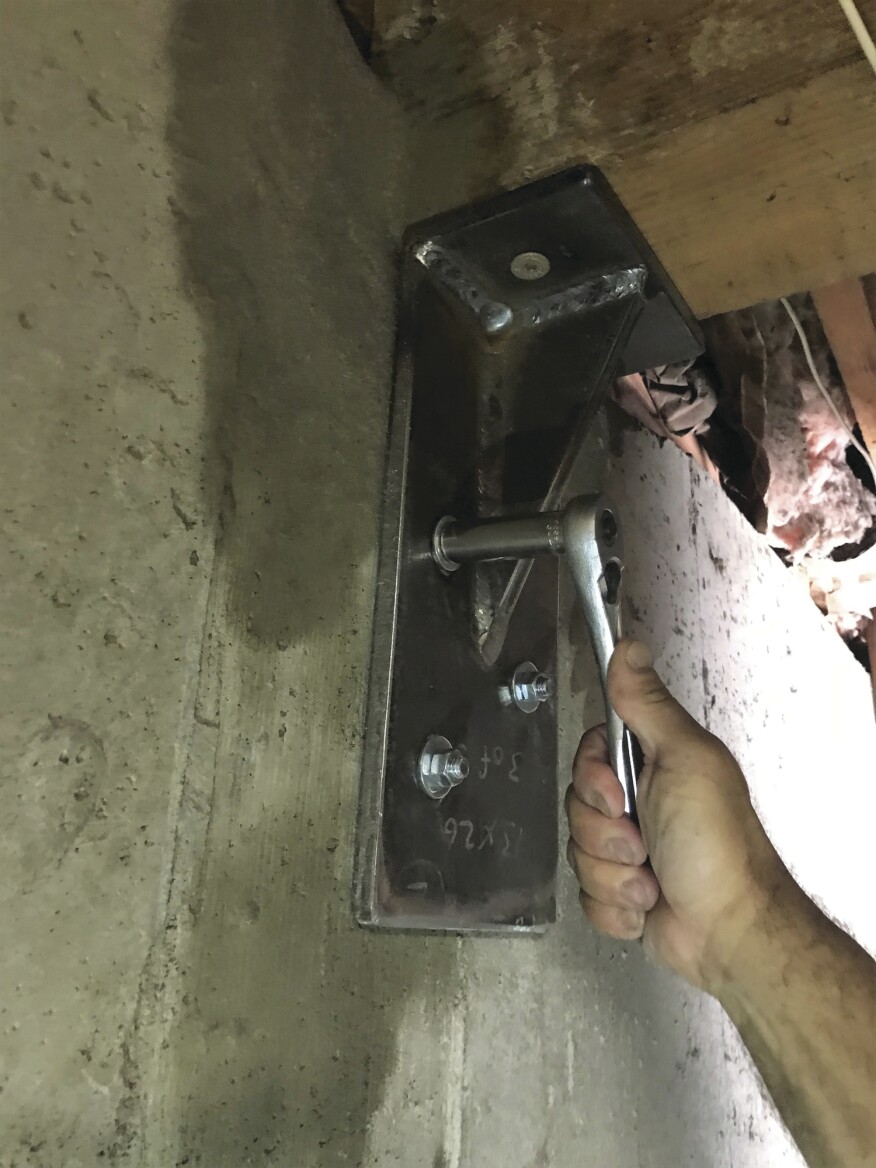
Wedge anchors have a nut and bolt at one end, and turning the nut expands a circular wedge on the other end that tightens the bolt in the hole. I inserted the three wedge anchors into their holes and tightened them (Simpson specifications require 60 foot pounds of torque) to secure the bracket in place. With the girder then safely secured at the proper level, the final step was removing the jack.
Photos by Emanuel Silva
How To Fix A Broken Support Beam
Source: https://www.jlconline.com/how-to/foundations/fixing-a-poorly-supported-beam_o
Posted by: hollowaycontaked.blogspot.com
0 Response to "How To Fix A Broken Support Beam"
Post a Comment